An audio amplifier is a device that reconstructs an input audio signal at a sound-producing output element, such as a speaker. The reconstructed signal should ideally maintain the original sound characteristics while delivering sufficient volume and power with high fidelity, efficiency, and minimal distortion. Since the audible frequency range is approximately 20 Hz to 20 kHz, an audio amplifier must provide excellent frequency response throughout this range.
One of the simplest analog implementations of an audio amplifier uses transistors operating in a linear mode to produce an output voltage proportional to the input voltage. The forward voltage gain is typically high, often exceeding 40 dB. When a feedback loop is incorporated around the gain stage, the overall loop gain becomes even higher. High loop gain is desirable because it improves amplifier performance by reducing distortion caused by nonlinearities in the forward path. In addition, feedback enhances Power Supply Rejection (PSR), helping to suppress noise originating from the power supply.
This article will systematically explore the basic structure, core operating principles, and typical applications of audio amplifiers, helping readers quickly understand their technical characteristics and performance differences.
The purpose of an audio amplifier is to reproduce an input audio signal at the desired volume and power level with high efficiency and low distortion through a sound-producing output device. An audio amplifier generally consists of two main sections: a preamplifier and a power amplifier.
Preamplifier
The signal amplitude from an audio source is usually very small and cannot directly drive a power amplifier. Therefore, it must first be amplified to an appropriate level using a preamplifier. In addition to signal amplification, a preamplifier often incorporates functions such as volume adjustment, tone control, loudness control, and channel equalization, allowing users to optimize audio performance according to specific requirements.
Power Amplifier
A power amplifier, often referred to simply as a power amp, is designed to provide sufficient current-driving capability to the load and deliver the required output power. Its primary function is power amplification, enabling speakers or other output devices to reproduce sound effectively.
Among various amplifier types, Class D amplifiers operate in a switching mode rather than a linear mode. In theory, they require little or no quiescent current, resulting in very high efficiency compared with traditional amplifier classes.
There are many types of audio power amplifiers, including Class A, Class B, Class AB, Class C, Class D, Class E, Class F, Class G, Class H, and Class S, etc. However, only a few of these amplifier classes are suitable for audio applications. The most commonly used audio amplifier types are Class A, Class B, Class AB, and Class D amplifiers.
A Class A amplifier is an amplifier in which the output device conducts current throughout the entire input signal cycle. Because it avoids switching-related nonlinearities, it offers excellent linearity and very low distortion when properly biased.
Its core characteristics are as follows: the quiescent operating point Q is positioned near the midpoint of the load line, keeping the transistor conductive across the full cycle of input signals. The topology can adopt single-ended or push‑pull configurations. Operating within the linear region of device characteristic curves, Class A produces minimal transient and crossover distortion alongside simple circuitry and easy calibration.
A single transistor supplies full load current throughout the entire AC cycle, corresponding to a conduction angle of 360°. Despite low distortion, Class A draws substantial quiescent current and suffers poor efficiency. Its theoretical maximum efficiency is limited to 25%, which necessitates heat sinks for thermal dissipation during operation.
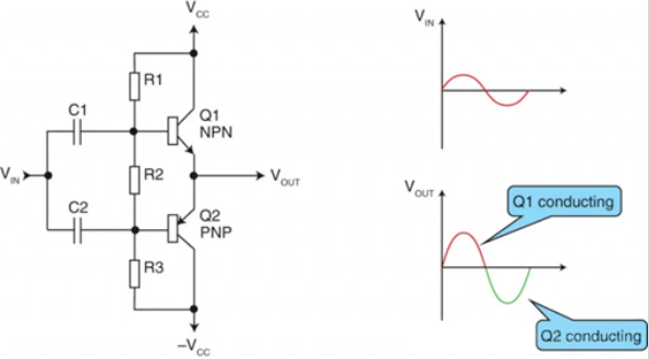
Class B amplifiers feature active devices conducting for 50% of the input signal cycle, and they represent the most widely used amplifier topology, accounting for roughly 99% of commercially manufactured amplifiers today.
A Class B power amplifier employs a pair of complementary transistors. Each device conducts during one half of the full signal cycle and turns off for the other half, resulting in a conduction angle of 180°. With no quiescent current consumption, Class B achieves high theoretical peak efficiency up to 78%. Nevertheless, transistors stay near their turn-on threshold when input signals approach zero, which introduces unwanted crossover distortion.
Class AB power amplifiers incorporate two diodes at the input stage of a Class B circuit. The diodes bias the output transistors into slight conduction even when the input signal is near zero, yielding a conduction angle between 180° and 360° for each transistor.
This configuration eliminates crossover distortion inherent to Class B designs and delivers efficiency falling between Class A and Class B. It is the dominant topology for conventional linear power amplifiers. Still, moderate output voltage remains well below supply rail voltage, causing considerable power dissipation across output transistors. As a result, even well‑optimized Class AB amplifiers cannot achieve high efficiency.
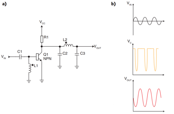
Class C amplifiers operate with active devices conducting for less than 50% of the input cycle and are mostly deployed for RF amplification. Built around a single transistor with customized biasing, the component switches on for only a small fraction of the full signal period, well below 50%. A band-pass filter at the output reconstructs the desired RF waveform from the distorted nonlinear output. The circuit contains no power-consuming resistive parts and consists solely of capacitors, inductors and the transistor.
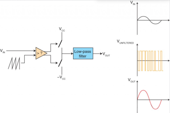
A Class D amplifier, also known as a switching amplifier, converts incoming analog audio or PCM digital data into PWM (Pulse Width Modulation) or PDM (Pulse Density Modulation) pulses. These pulses govern the on-off state of high-power switching devices to deliver amplified audio power, featuring remarkably high efficiency.
Its output stage uses two complementary power transistors driven by high-frequency control pulses. The two devices operate in alternating switching mode: one turns on while the other shuts off. Zero quiescent power loss enables outstanding efficiency. While the theoretical peak efficiency hits 100%, practical implementation exceeds 80%, two to three times higher than conventional linear amplifiers.
Functionally, digital Class D amplifiers act as 1-bit power digital-to-analog converters. The full circuit comprises four core modules: input signal conditioning, pulse modulation generation, high-power switching stage (half-bridge or full-bridge topologies), and LC low-pass output filter. Class D amplifiers amplify audio signals via high-frequency switching circuitry.
Both Class E and Class F are optimized variants derived from Class C amplifiers, built on the principle that the transistor conducts for only a portion of the AC cycle. The transistor sustains minimal voltage across its terminals during conduction and turns off before voltage rises substantially, cutting power dissipation fundamentally.
- Class E: Delivers 80% to 90% efficiency with comparatively straightforward circuitry, making it a widely adopted option for high-efficiency RF amplification.
- Class F: Leverages multi-resonant networks to refine voltage and current waveforms, yielding a theoretical efficiency close to 100%. Its downsides include complicated circuit layout and tight tolerance requirements for passive components.
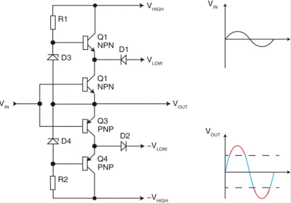
Class G and Class H amplifiers are developed to tackle excessive power dissipation inherent to Class AB designs. High-output power demands high supply voltage, yet constant high voltage causes unnecessary power waste at low signal levels. Both topologies resolve this drawback by dynamically adjusting supply rails.
- Class G: Equipped with two or more discrete fixed supply rails; low-power operation draws from the lower rail, while the circuit switches to the high-voltage rail for high-output scenarios.
- Class H: Supply rail voltage varies continuously following input signal amplitude instead of fixed-level switching, matching power supply closely to instantaneous signal requirements and further cutting power loss.
Class S amplifiers were named by Dr. Sandman. This architecture features a Class A stage with limited current capacity backed up by a Class B amplifier. The circuit configuration presents a relatively high equivalent resistance at the load terminal.
Different classes of power amplifiers adopt distinct working principles and circuit designs. The table below summarizes the core pros, cons, and mainstream application fields of Class A through Class H amplifiers for intuitive comparison.
| Amplifier Class | Advantages | Limitations | Typical Applications |
| Class A | Excellent linearity, simple circuit structure | Extremely low efficiency (≈30%) | High-end audio reference modules, precision small-signal amplification |
| Class B | High efficiency, zero power consumption with no input signal | Severe crossover distortion | Medium-power scenarios requiring low distortion |
| Class AB | Balanced efficiency and linearity, low cost | Lower efficiency than Class B and inferior linearity versus Class A | Low-cost audio equipment (regular speakers, earphones) |
| Class C | High efficiency (60%–70%), low component cost | Severe non-linearity, mandatory filtering required | RF remote controllers, RFID, basic wireless communication |
| Class D | High power density, good compatibility with digital signals | Requires anti-aliasing design and EMC optimization | Medium & high-power audio (home / automotive audio systems) |
| Class E | Superior RF efficiency (80%–90%), straightforward topology | Restricted exclusively to RF applications | Base stations, RF power amplifier modules |
| Class F | Near 100% theoretical efficiency | Intricate circuitry, strict precision requirements for components | High-precision RF systems (radars, premium base stations) |
| Class G | Higher efficiency than Class AB, lower cost than Class H | Distortion prone during power supply rail switching | Professional audio, mid-to-high grade automotive power amplifiers |
| Class H | Among the most efficient linear amplifier topologies | Complex control circuitry, elevated manufacturing cost | Premium professional audio, precision power amplification |
An audio amplifier takes a low-voltage, weak electronic audio signal (from sources like smartphones, laptops, CD players, or turntables) and boosts its electrical power enough to physically drive and move the cones inside your speakers to create sound.
For general audio applications, Class A, Class AB and Class D are considered the best choices.
Class A offers the highest linearity and lowest distortion, making it ideal for high-end audiophile systems, but it is very inefficient and generates significant heat.
Class AB provides a good balance between sound quality and efficiency, which is why it is the most widely used in traditional hi-fi and consumer audio systems.
Class D amplifiers are highly efficient and compact, making them dominant in portable devices, TVs, and modern powered speakers, though early designs had higher distortion compared to linear classes.
Class C conducts for less than 50% of the signal cycle and uses LC components with a band-pass filter to reconstruct the output waveform.
Class E improves efficiency by switching the transistor when the voltage is very low, achieving about 80%–90% efficiency with relatively simple circuitry.
Class F uses multi-resonant networks to shape voltage and current waveforms, offering theoretical efficiency close to 100%, but with higher design complexity and tight component tolerances.