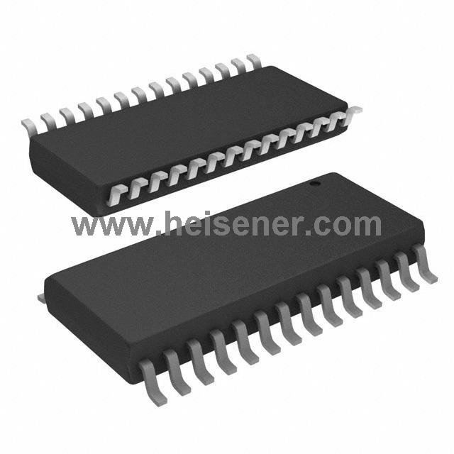
IR2130S Introduction
The IR2130S is a high-voltage, high-speed driver IC designed for controlling power MOSFETs and IGBTs, featuring three independent high-side and low-side output channels. It supports operation up to 600V, using proprietary HVIC technology for robust monolithic construction.
This IC is compatible with CMOS/LSTTL logic inputs down to 2.5V and includes a ground-referenced operational amplifier for bridge current feedback via an external sense resistor. Key features include a current trip function that disables all outputs during over-current conditions and an open-drain FAULT signal for shutdown indications. Matched propagation delays and high pulse current output stages optimize performance in high-frequency applications.
IR2130S Symbol

IR2130S Footprint

IR2130S 3D Model

IR2130S Pinout

HIN1,2,3: Logic inputs for high side gate driver outputs (HO1,2,3), out of phase
LIN1,2,3: Logic inputs for low side gate driver output (LO1,2,3), out of phase
FAULT: Indicates over-current or undervoltage lockout (low side) has occurred, negative logic
VCC: Low side and logic fixed supply
ITRIP: Input for over-current shutdown
CAO: Output of current amplifier
CA-: Negative input of current amplifier
VSS: Logic ground
VB1,2,3: High side floating supplies
HO1,2,3: High side gate drive outputs
VS1,2,3: High side floating supply returns
LO1,2,3: Low side gate drive outputs
VS0: Low side return and positive input of current amplifier
IR2130S Typical Connection

IR2130S Functional Block Diagram

IR2130S Specification
| Parameter | Value |
| Channel Type | 3-Phase |
| Number of Drivers | 6 |
| Supply Voltage | 10V ~ 20V |
| Logic Voltage - VIL, VIH | 0.8V, 2.2V |
| High-Side Floating Supply | 600V |
| Current - Peak Output (Source, Sink) | 250mA, 500mA |
| Propagation Delay | 750ns (typical) |
| Rise / Fall Time | 80ns, 35ns |
| Deadtime | Programmable |
| FAULT Signal | Open-Drain Output |
| Current Feedback | Via Operational Amplifier |
| Package | 28-SOIC |
| Operating Temperature | -40°C ~ 150°C |
IR2130S Features
Floating channel designed for bootstrap operation
Fully operational to +600V
Tolerant to negative transient voltage
dV/dt immune
Gate drive supply ranges from 10 to 20V
Undervoltage lockout for all channels
Over-current shutdown turns off all six drivers
Independent half-bridge drivers
Matched propagation delay for all channels
2.5V logic compatible
Outputs out of phase with inputs
Cross-conduction prevention logic
Also available LEAD-FREE
IR2130S Applications
Motor Control Systems
Inverters
Uninterruptible Power Supplies (UPS)
Power Supplies
HVAC Systems
Electric Vehicles
Industrial Automation
IR2130S Package
The IR2130S uses a 28-SOIC package, a standard surface-mount package featuring high integration and compact size, ideal for space-constrained circuit designs. The package width is 7.5mm, with a thickness of approximately 2.35mm, offering low thermal resistance. Additionally, its 28 pins are arranged compactly to ensure efficient signal transmission and stable electrical performance.
The 28-SOIC package of the IR2130S provides excellent mechanical strength and soldering reliability, making it suitable for automated reflow soldering processes. With a pin pitch of 1.27mm, it simplifies layout design and reduces wiring complexity.

How to Use IR2130S?
First, connect VCC to the low-side driver and logic power supply, and VB1, VB2, VB3 to the high-side floating supplies. Ensure all ground connections are correctly established, including VSS as the logic ground, VS1, VS2, VS3 as the return paths for the high-side floating supplies, and VS0 for the low-side return and the positive input of the current amplifier. Use filter capacitors during power connection to minimize noise interference.
Next, connect HIN1, HIN2, HIN3 to the high-side drive signals, and LIN1, LIN2, LIN3 to the low-side drive signals. The logic inputs are compatible with CMOS or LSTTL outputs, with a minimum input voltage of 2.5V. HO1, HO2, HO3 serve as high-side driver outputs, while LO1, LO2, LO3 are low-side driver outputs. To prevent cross-conduction, ensure proper synchronization of the input signals.
Connect the ITRIP pin to a current-sensing resistor to set the overcurrent protection threshold. CA- and CAO form an operational amplifier to monitor bridge current. The FAULT pin provides a signal for overcurrent or undervoltage lockout, which can be connected to external logic circuits for fault detection. Finally, carefully inspect the setup, power on the circuit, test its functionality, and fine-tune the parameters.
FAQs
What is the purpose of IR2130S?
The IR2130S is a high-voltage, high-speed MOSFET and IGBT driver with three independent high and low-side channels, designed for motor control and power management applications.
What are its key protection features?
It includes overcurrent protection (ITRIP), undervoltage lockout, and a fault reporting function via the FAULT pin.
How does IR2130S handle cross-conduction prevention?
It features matched propagation delays and high pulse current buffer stages to minimize driver cross-conduction.