A voltage regulator is a device used to maintain a stable output voltage. It typically consists of a voltage regulation circuit, a control circuit, and a servo motor. When the input voltage or load changes, the control circuit samples, compares, and amplifies the voltage signal, then drives the servo motor to adjust the position of the carbon brush on the regulator. By automatically changing the coil turns ratio, the output voltage is kept stable.
Today, let's explore the structure of voltage regulators, their functions, and how to build their circuits in modern electronic systems.
A voltage regulator is a power supply circuit or device that can automatically adjust its output voltage. Its function is to stabilize input voltages that fluctuate widely or do not meet the requirements of electrical equipment, bringing them within a set range so that various circuits or devices can operate normally at their rated voltage.
The structure of a voltage regulator typically includes the following main components:
- Rectifier Bridge: The input of a voltage regulator usually requires a rectifier bridge to convert AC power into DC power.
- Filter Capacitor: After the rectifier bridge, a filter capacitor is needed to smooth the output voltage and remove high-frequency noise from the power line.
- Reference Voltage Source: The regulator requires a reference voltage source to provide a stable reference voltage. This is used to compare the output voltage with the reference voltage, helping maintain a stable output.
- Error Amplifier: The error amplifier is typically used to amplify the difference between the output voltage and the reference voltage and feed it back into the regulator’s control circuit to adjust the output voltage.
- Control Circuit: The regulator’s control circuit usually includes a regulator IC, which can maintain output voltage stability based on the feedback signal from the error amplifier.
- Power Transistor: The power transistor is generally used to adjust the output voltage and keep it stable.
- Output Capacitor: After the power transistor, an output capacitor is required to smooth the output voltage and remove high-frequency noise from it.
- Protection Circuit: Voltage regulators usually include protection circuits to prevent overvoltage, overcurrent, and overheating, thereby protecting both the regulator and the connected load.
The main role of a voltage regulator is to provide a stable output voltage for electronic devices. When power supply voltage fluctuates or fails, the regulator offsets noise and instability to prevent damage to components. Many regulators also include overvoltage and overcurrent protection to avoid overloading or overheating, which extends the device's lifespan.
By maintaining a steady output, regulators ensure that circuits operate within their normal range, preventing performance drops, data loss, or other failures. Furthermore, they provide "clean" power by filtering out noise and interference, improving signal quality and overall efficiency.
Voltage regulators guarantee a reliable power supply for every module and component. This is essential for the stable operation and performance optimization of industrial equipment, precision instruments, and various electronic products.
A Zener diode is a type of diode that, when connected in a reverse-biased configuration (as shown in the figure below), begins to “break down” or conduct at a specific voltage known as the Zener voltage. Once it starts conducting, it does not limit the current by itself, so a resistor (R1, as shown) is required to limit the current to a safe level.
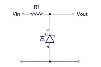
In the simple voltage regulator above, Vin is 12 V, Vout is 5 V, and the load current I is 10 mA.
If there were no Zener diode, R1 would be calculated as R = (V / I) = (12 − 5) / 0.01 = 700 Ω.
However, the Zener diode would not conduct under this condition. As a rule of thumb, a Zener diode needs to conduct two to five times the load current, for example, 50 mA. Therefore, the total current should be
I = 50 mA + 10 mA = 60 mA, which gives R1 = 7 / 0.06 ≈ 116 Ω.
The problem is that at higher load currents, the power dissipation in R1 and D1 becomes excessive. Nevertheless, this circuit is very suitable for level-shifting applications, such as converting a 5 V signal to 3.3 V.
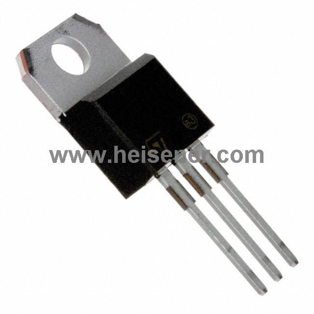
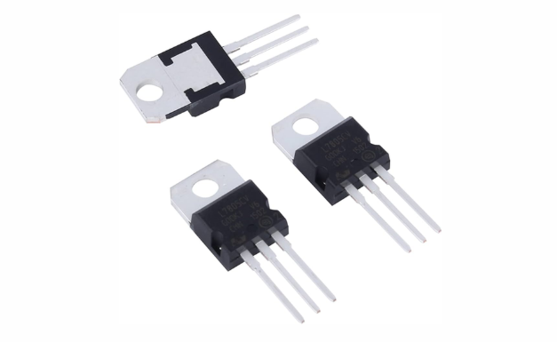
In circuits, there are fixed-voltage three-terminal regulators. The M78xx series of regulator ICs come in various output voltages. For example, the LM7812 outputs 12 V, the LM7809 outputs 9 V, and the LM7805 outputs 5 V.
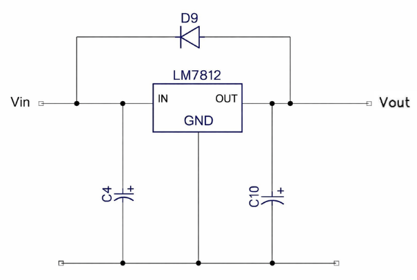
Do not confuse C4 and C10 with the smoothing capacitors; they are used for noise reduction and stability and should be low-ESR (Equivalent Series Resistance) types. Typically, C4 is 10 µF and C10 is 1 µF. Note that diode D9 is used to discharge any large capacitors in the load in reverse, preventing the regulator from being reverse-biased when the input voltage drops.
Finally, an adjustable three-terminal regulator—the well-known LM317 regulator.
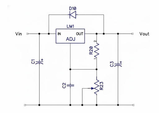
C2 is used for noise suppression and can be 1 µF. The ratio of R20 to R23 sets the output voltage. These can be two fixed resistors or one fixed resistor and one adjustable potentiometer. In the datasheet, R20 is specified as a non-standard 240 Ω, but if it is set to the standard 220 Ω, then for any voltage between V min and V max: R7=(176×Vout)−220
Voltage regulators are widely used in various electronic devices and industrial control systems. For example, in computers, communication equipment, and laboratory instruments, regulators provide a constant voltage, allowing electronic components and circuits to work normally at their rated conditions. This helps prevent faults or performance drops caused by voltage fluctuations.
In addition, voltage regulators play an important role in home appliances, medical devices, automated control systems, and new energy power supplies. By filtering power noise, stabilizing the output voltage, and providing overvoltage and overcurrent protection, regulators not only improve the safety and reliability of devices but also enhance the overall performance and lifespan of the system.
1. One possible reason is high summer temperatures. As the weather gets hotter, voltage regulators can become hotter too. The main component inside a regulator is the transformer, made of silicon steel sheets and winding wire. High-quality transformers use copper wire, while cheaper ones may use aluminum. When the regulator powers a load, current flows through the transformer windings, which naturally generates heat.
2. Since all wires have some resistance, it is normal for the voltage regulator to generate heat when supplying a load. As long as it is not overloaded and the temperature does not exceed 120 °C, this heating is normal and safe. Therefore, it is recommended to use a voltage regulator at about 70% of its rated power, which can help extend the service life of the device.
In summary, it is normal for a voltage regulator to generate heat. As long as it is used properly, not overloaded, and kept within a safe temperature range, it can be used safely, and operating it below its rated capacity can help extend its lifespan.